使用 Arduino 实现 PID 控制器
PID controller implementation using Arduino (microcontrollerslab.com)
In this article, you will learn how to design PID controller using Arduino. PID controller can implemented using both analog and digital electronics. But in this tutorial, you will see the implementation of PID controller using Arduino development board. you will see it is very easy to design a proportional integral derivative controller using a microcontroller board like Arduino than using analog electronics. If you are reading this article, you surely know about feedback control system. Proportional integral derivative controller has many application in motor speed control, digital temperature controller and in many power electronics projects.
在本文中,您将学习如何使用 Arduino 设计 PID 控制器。 PID 控制器可以使用模拟和数字电子技术实现。 但在本教程中,您将看到使用 Arduino 开发板实现 PID 控制器。您会发现,使用 Arduino 等微控制器板设计比例积分导数控制器比使用模拟电子设备更容易。如果您正在阅读这篇文章,那么您一定了解反馈控制系统。 比例积分导数控制器在电机速度控制、数字温度控制器和许多电力电子项目中都有广泛应用。
Introduction to PID controller
So let’s start off with the process. To understand PID controller, you first need to understand few concepts of feedback control system. A process in the control theory is a system whereby an applied input generates an output.So let’s take a visual system for example as our process. Our process consists of a throttle actuator which feeds fuel into the engine. Our input to the system is the angle of the gas pedal and our output is the speed or velocity of a vehicle. The greater the angle the faster the vehicle will go. The smaller the angle the slower the vehicle will go. This is an example of open loop control system.Now as far as this process is concerned, the driver’s actuation of the gas pedal is fully responsible for how slow or fast the vehicle will go. But what if we want to regulate speed at a constant velocity without actuating the gas pedal ourself ?
因此,让我们从过程开始。要理解 PID 控制器,首先需要了解反馈控制系统的一些概念。 在控制理论中,过程是一个输入产生输出的系统。 我们的过程包括一个向发动机供油的节气门执行器。 我们对系统的输入是油门踏板的角度,输出是车辆的速度。 角度越大,速度越快。 角度越小,速度越慢。 这就是开环控制系统的一个例子。就这一过程而言,驾驶员对油门踏板的踩踏完全决定了车辆行驶的快慢。 但是,如果我们想在不踩油门踏板的情况下匀速行驶,该怎么办呢?
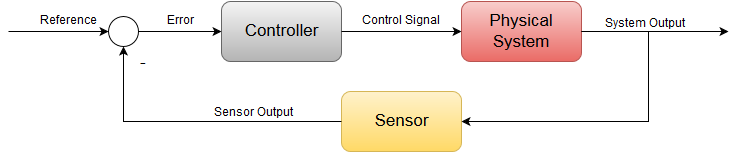
This is achieved using a closed loop feedback system commonly known as cruise control.To integrate cruise control to this process we will need to add a few more elements to the system block. First we start off by sensing the speed using a sensor or in this case a speedometer.The sensed speed the speedometer provides is compared with a set point or a desired speed to generate an error term.This error term is then fed into a controller which generates an actuation signal to drive the throttle and thus we have a feedback loop.
要将巡航控制集成到这一过程中,我们需要在系统模块中添加一些元素。 首先,我们使用传感器(在本例中为车速计)感知车速。车速计提供的感知车速与设定点或期望车速进行比较,从而产生误差项。
How PID controller works?
Now let’s say it’s some instance the vehicle is moving at 70 miles per hour. But we set our cruise control set point to 75. The actual speed is fed back and subtracted from our set point and we get a positive error of plus five. This positive error goes into the controller to generate a positive actuation signal to the throttle. Now this will allow more fuel into the engine and will cause the vehicle to go fast enough to reach the desired set point of 75 and our error will converge down to zero. This is the power of negative feedback control.
假设车辆以每小时 70 英里的速度行驶。但我们将巡航控制的设定点设置为 75 英里。 实际速度从我们的设定点反馈并减去后,我们得到了正 5 的正误差。 这个正误差进入控制器,为节气门产生一个正的驱动信号。 现在,这将使更多的燃油进入发动机,并使车辆以足够快的速度达到所需的设定点 75,我们的误差也将收敛为零。 这就是负反馈控制的威力。
Now the same situation can happen vice versa where if the vehicle is going faster than our set point. So let’s say at 80 miles per hour. You’ll get a negative error term of negative 5. And thus our controller will provide a decrease throttle signal to slow down the vehicle back to 75. And again the error will converge down to zero. So it’s pretty apparent from this example that the controllers functionality is to essentially take our error signal and generate a control signal to drive our process. In doing so our actual output should eventually reach our desired set point and thus the error should converge down to zero.
反之亦然,如果车辆的速度超过了我们的设定值。比方说,以每小时 80 英里的速度行驶。 你会得到负 5 的负误差项。 因此,我们的控制器将提供一个减小油门的信号,使车辆减速至 75。 误差将再次趋于零。 因此,从这个例子中我们可以很明显地看出,控制器的功能主要是接收误差信号,并生成控制信号来驱动过程。 这样,我们的实际输出最终应达到我们所需的设定点,因此误差应趋于零。
What is the purpose of PID controller ?
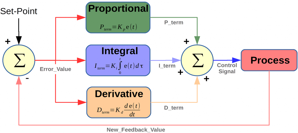
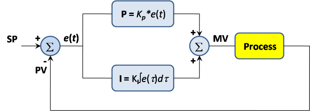
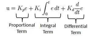
Now the subject of this tutorial is to understand the famous controller used in most feedback control systems. The Proportional integral and Derivative controller or better known as the PID controller. The PID controllers job is to essentially take this error signal and perform three separate mathematical operations on it. Sum up the results and cleverly produce an output that will drive the system or process to the desired setpoint. The controller can be mathematically written out as shown where a control signal is a summation of three mathematical operations. The term involves taking the error and multiplying it by a constant Kp. The integral term involves integrating the error over time and the derivative term involves taking the derivative of the error.
本教程的主题是了解大多数反馈控制系统中使用的著名控制器。 比例积分和微分控制器,或更广为人知的 PID 控制器。 PID 控制器的工作主要是接收误差信号,并对其执行三个独立的数学运算。 将结果相加,巧妙地产生一个输出,从而驱动系统或过程达到所需的设定点。 如图所示,控制器可以用数学方法写出,其中控制信号是三个数学运算的总和。 误差项是将误差乘以常数 Kp。 积分项涉及误差随时间的积分,导数项涉及误差的导数。
Now you can see that each term has a constant in front of it. These are known as the tuning constants, and are the essential design parameters that if chosen properly will allow the controller to output a control signal that will bring the error down to zero. But when assessing a control system having the error term go down to zero is not the only goal. Because although you can adjust these parameters such that the error is driven to zero. Poor tuning of these constants can cause overshooting the desired set point, long settling time, and even in some cases instability or oscillations.
现在你可以看到,每个项前面都有一个常数。这些常数被称为调谐常数,是重要的设计参数,如果选择得当,控制器就能输出控制信号,将误差降至零。 但在评估控制系统时,将误差项降至零并不是唯一的目标。 因为尽管可以通过调整这些参数来使误差趋于零,但如果调整不当,也会导致误差过大。 如果对这些常量的调整不当,可能会导致过冲所需的设定点、沉淀时间过长,甚至在某些情况下出现不稳定或振荡。
Proportional controller
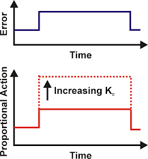
Now I will discuss P or proportional term of the PID controller. As you see in block diagram of PID controller, the error essentially goes through each PID block and their outputs are summed up and form a control signal that drives the process to the desired setpoint. But in order to understand the advantage and disadvantage of using one or more term, we will break down the controllers operation by dealing with each term separately. Now lets see how a closed loop system performs with just proportional control. So let’s say we have a positive step change in the setpoint and therefore we get a positive error. Since all the P controller does is multiply the error by the control constant Kp. It’s quite apparent why this is known as proportional control because with a fixed Kp constant the control signal is proportional to the error. If our errors large, we’ll get a large control signal if our errors are small. we’ll get a small control signal. And thus we can adjust our control effort by simply increasing or decreasing this Kp constant.
现在我将讨论 PID 控制器的 P 或比例项。 正如您在 PID 控制器框图中所看到的,误差基本上会经过每个 PID 模块,然后将它们的输出相加,形成一个控制信号,驱动过程达到所需的设定点。 但是,为了了解使用一个或多个术语的优缺点,我们将通过分别处理每个术语来分解控制器的运行。 现在,让我们来看看仅使用比例控制的闭环系统是如何运行的。 假设设定点发生了正阶跃变化,因此产生了正误差。 由于 P 控制器所做的只是将误差乘以控制常数 Kp。很明显,这就是所谓的比例控制,因为在固定的 Kp 常量下,控制信号与误差成正比。 如果误差大,控制信号就大,如果误差小,控制信号就小。 因此,我们只需增大或减小 Kp 常量,就能调整控制力度。
Main disadvantage of proportional control is that we can never drive the error to zero because that would mean our control effort is zero. Now there is a way to remove the offset or bring the error to zero. Looking at the normal structure of the controller if we were to add a bias signal to our controllers output, this can potentially drive the process enough such that we reach our desired setpoint. But the disadvantage of this method is that for every new set point we’re going to have to manually change the bias. Now although the proportional controller is easy to implement and can drive the process close to our setpoint, it can never eliminate the offset automatically. This issues can be automatically solved by adding integral controller.
比例控制的主要缺点是,我们永远无法将误差降至零,因为这意味着我们的控制努力为零。 现在有一种方法可以消除偏移或使误差为零。 从控制器的正常结构来看,如果我们在控制器的输出中加入一个偏置信号,就有可能驱动整个过程,从而达到我们所需的设定点。 但这种方法的缺点是,每增加一个新的设定点,我们就必须手动改变偏置。 现在,虽然比例控制器很容易实现,并能使过程接近设定点,但它永远无法自动消除偏置。 这个问题可以通过添加积分控制器来自动解决。
Proportional Integral controller
It is used to mediates some of the flaws of the proportional controller. P controllers main flaw was its inability to bring the steady state error to zero. we have this steady state error AND we need a controller to somehow act on it in a way that will allow our control signal to accumulate until the desired setpoint is reached. This is easily achieved by taking the integral of the error. Let’s add the integral term to our original controller to form a PI controller.
它用于弥补比例控制器的一些缺陷。 比例控制器的主要缺陷是无法将稳态误差降至零。我们有了这个稳态误差,我们需要一个控制器,以某种方式对其采取行动,让我们的控制信号不断累积,直至达到所需的设定点。 利用误差的积分就可以轻松实现这一目标。 让我们将积分项添加到原始控制器中,形成一个 PI 控制器。
The main advantage of integral control is that it allows us to eliminate the steady state error completely. Now by tuning the Ki term we can adjust the control effort of our integral controller. Now in this case for a high Ki value, we can see that we get a steeper slope and this would make our control signal more aggressive.
积分控制的主要优点是可以完全消除稳态误差。 现在,通过调整 Ki 项,我们可以调整积分控制器的控制力度。 在这种情况下,如果 Ki 值较高,我们可以看到斜率会更陡峭,这将使我们的控制信号更加激进。
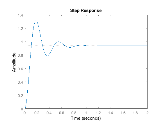
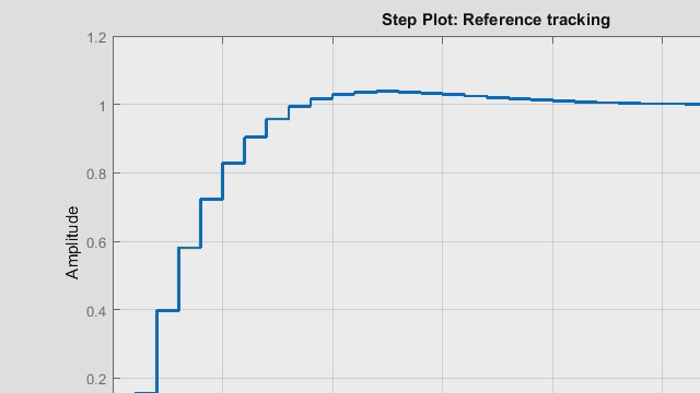
Now just like with proportional control, we can’t just arbitrarily choose an integral constant. The output behaves relatively upon varying the integral constant. If Ki is too low, we end up with the large rise time and overall a very slow response. This is bad when it comes to rejecting disturbances or constant changes in the set point. You can see we reached our set point much sooner with just a small amount of overshoot. But in an attempt to get a faster response, increasing this gain even further can lead to larger overshoots and this should be avoided when trying.
we learned that the proportional controller provided us with a fast rise time but with a steady state offset. The PI controller solves that using the integral control to reduce the error to zero. But when neither the controller can solve is the large overshoots and ringing. In order to reduce or dampen this response, we will need to add a differential controller and they’ll quickly respond fast enough to keep the output from overshooting or undershooting the set point.
现在,就像比例控制一样,我们不能随意选择一个积分常数。 在改变积分常数时,输出会有相对的变化。 如果 Ki 太低,则上升时间较长,总体响应速度较慢。 这不利于抑制干扰或设定点的持续变化。 您可以看到,我们只需少量的过冲就能更快地达到设定点。 但是,为了获得更快的响应,进一步提高增益会导致更大的超调,在尝试时应避免这种情况。 PI 控制器利用积分控制将误差减小到零,从而解决了这一问题。 但这两种控制器都无法解决的问题是大的过冲和振铃。 为了减少或抑制这种响应,我们需要增加一个差分控制器,它们能快速响应,使输出不会过冲或下冲设定点。
Proportional integral derivative controller
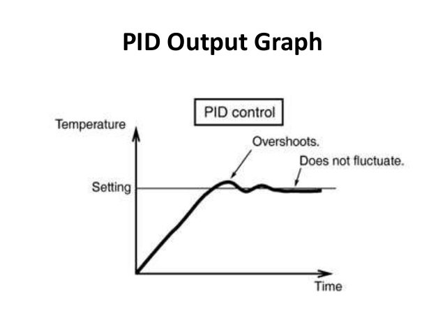
We have seen that P controller eliminates the stay state error through the interval term. But we also made it clear that neither the p term or I term can contribute to actively dampening the overshoots. This is where the derivative comes into play. Let’s look at how this new term handles the error signal the job of the derivative term is to take the rate of change of the error as its control signal. The proportional term decreases the rise time the interval term eliminates a steady state error and the derivative term reduces the overshoots and ringing.
我们已经看到,P 控制器通过区间项消除了停留状态误差。 但我们也清楚地看到,无论是 P 项还是 I 项,都无法主动抑制过冲。 这就是导数发挥作用的地方。 导数项的工作是将误差的变化率作为其控制信号。 比例项缩短了上升时间,间隔项消除了稳态误差,导数项则减少了过冲和振铃。
Now that we have understand PID controller and its three terms. Now lets see how to implement PID controller using Arduino.现在我们已经了解了 PID 控制器及其三个术语。 现在让我们看看如何使用 Arduino 实现 PID 控制器。
Implementing PID controller using Arduino
Now, I’ll be going over how to implement a PID controller in code on the Arduino. The mathematical equation written here is a controller expressed in continuous time or in the analog domain.
现在,我将介绍如何在 Arduino 上用代码实现 PID 控制器。 这里所写的数学公式是以连续时间或模拟域表示的控制器。
Now studying the controller in the continuous or analog domain makes it easier for us to realize what is going on. But most controllers these days are implemented digitally or with microcontroller like Arduino in software. So we want to implement this PID controller on the Arduino. We are going to have to convert it to the discrete time or digital domain as we can see here.
现在,研究连续域或模拟域中的控制器更容易让我们意识到发生了什么。 但如今大多数控制器都是通过数字方式或 Arduino 等微控制器软件实现的。 因此,我们要在 Arduino 上实现这个 PID 控制器。 我们必须将其转换为离散时域或数字域,如图所示。
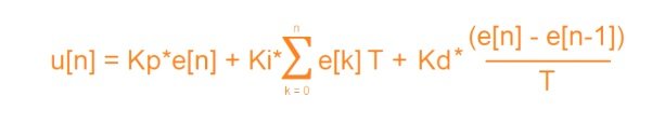
Not much has changed at all since we’re in the digital domain. We must treat each signal as a discrete sample. Because arduino will measure feedback signal in digital form. The proportional term is just the gain multiplied by the discrete error signal. The integral term is now a Sigma summation and the dreaded term is simply the difference between the current error and the previous error. Now in the digital domain graphically our control signal looks like this.
自从我们进入数字领域以来,情况并没有发生多大变化。我们必须将每个信号视为离散样本。 因为 arduino 将以数字形式测量反馈信号。比例项只是增益乘以离散误差信号。 积分项现在是西格玛求和,而可怕的项只是当前误差与前一个误差之间的差值。 现在,在数字域中,我们的控制信号看起来是这样的。
Now as you can see here to the control signal of N is computed discretely every t seconds in time. This case T is a sampling time or a fixed time interval. The controller takes to compute a new value for the output. And if we take a look at the discrete equation again this capital T is essentially the delta t of the continuous domain. Now because in the loop we’re going to call the function in intervals of t seconds. We can treat this as a fixed constant and this will be a lot clearer when I get to the coding part in Arduino IDE.
如图所示,N 的控制信号每隔 t 秒计算一次。这里的 T 是采样时间或固定的时间间隔。 控制器需要计算一个新的输出值。 如果我们再看一遍离散方程,资本 T 本质上就是连续域的 delta t。 在循环中,我们将以 t 秒为间隔调用函数。 我们可以将其视为一个固定常数,这一点在我使用 Arduino IDE 进行编码时会更加清楚。
PID controller code for Arduino
So here we have the PID controller algorithm written out on the Arduino ID.
double sensed_output, control_signal;
double setpoint;
double Kp;  //proportional gain
double Ki;  //integral gain
double Kd;  //derivative gain
int T;      //sample time in milliseconds (ms)
unsigned long last_time;
double total_error, last_error;
int max_control;
int min_control;void setup() {
}void loop() {PID_Control();  //calls the PID function every T interval and outputs a control signal
}void PID_Control() {unsigned long current_time = millis();  //returns the number of milliseconds passed since the Arduino started running the programint delta_time = current_time - last_time;  //delta time intervalif (delta_time >= T) {double error = setpoint - sensed_output;total_error += error;  //accumalates the error - integral termif (total_error >= max_control) total_error = max_control;else if (total_error <= min_control) total_error = min_control;double delta_error = error - last_error;  //difference of error for derivative termcontrol_signal = Kp * error + (Ki * T) * total_error + (Kd / T) * delta_error;  //PID control computeif (control_signal >= max_control) control_signal = max_control;else if (control_signal <= min_control) control_signal = min_control;last_error = error;last_time = current_time;}
}
I’ll now proceed to explain the code line by line. So first we start off by defining a variables needed for the computation. And you’ll notice most of these are of the double data type or floating point. This is needed because it allows more precise computation. Now just to make things easier I kept the computation of the control signal in a separate function called the control. Now in order to make sure that we get a uniform interval of sample time t we first start off by storing the current time the program has been running by using a built in function in Arduino IDE called millies. This function essentially gives you the number of milliseconds passed since the start of the program. we can keep track of the current time we can compute the delta time by subtracting the current time from the previous time now to get the updated control signal every t seconds.
下面我将逐行解释代码。首先,我们定义计算所需的变量。 你会发现这些变量大多是 double 数据类型或浮点型。 这样做是有必要的,因为这样可以进行更精确的计算。 为了方便起见,我将控制信号的计算放在了一个名为 control 的单独函数中。 为了确保采样时间 t 间隔一致,我们首先使用 Arduino IDE 中名为 millies 的内置函数存储程序当前运行的时间。该函数主要提供自程序开始运行以来所经过的毫秒数。我们可以跟踪当前时间,用当前时间减去之前的时间,计算出 delta 时间,从而获得每 t 秒更新一次的控制信号。
we have an IF condition whereby if the time interval during the loop equals or exceeds t the control signal is computed and updated. This if condition is what allows the controller to get called FBT seconds and it makes realizing the controller a lot easier. Our error term is simply the set point minus the sensed output the total error refers to the integral term of accumulating the error. Every t seconds the Delta error refers to the derivative term whereas just a current error minus the last error. So what those values are computed and obtain a we can sum them up to form our control signal. And you can see here that the summation is pretty much the same as shown in the discrete expression. So what’s the control signals computed. We actually store the error as last error for the next iteration. And the same goes for the time. This pretty much covers how the control algorithm is implemented or on the order.
我们有一个 IF 条件,如果循环中的时间间隔等于或超过 t,就会计算和更新控制信号。 这个 if 条件使得控制器可以称为 FBT 秒,也使得控制器的实现变得更加容易。我们的误差项只是设定点减去感应输出,总误差指的是误差累积的积分项。 每 t 秒的 Delta 误差指的是导数项,而只是当前误差减去上次误差。 因此,计算出这些值后,我们就可以将它们相加,形成我们的控制信号。 你可以看到,这里的求和与离散表达式中显示的基本相同。 那么计算出的控制信号是什么呢? 实际上,我们将误差作为下一次迭代的最后一次误差进行存储。 时间也是如此。 这几乎涵盖了控制算法的执行方式或订单。