stm32 - GPIO
- GPIO结构图
- GPIO原理图
- 输入
- 上拉/下拉/浮空
- 施密特触发器
- 片上外设
- 输出
- 推挽/开漏/关闭输出方式
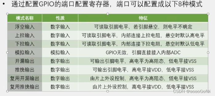
- GPIO88种模式
- 复用输出
- GPIO寄存器
- 端口配置寄存器_CRL
- 端口输入数据寄存器_IDR
- 端口输出数据寄存器_ODR
- 端口位设置/清除寄存器_BSRR
- 端口位清除寄存器_BRR
- 端口配置锁定寄存器
- 例子
- 点灯
- 流水灯
- 蜂鸣器
- 按键和灯
- 蜂鸣器和光敏电阻
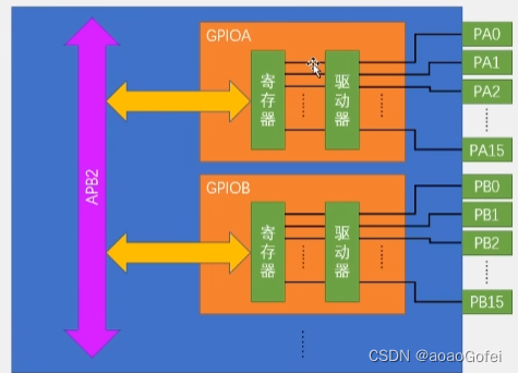
GPIO结构图
GPIO全都挂载在APB2总线上的
每个GPIOA 都有16个引脚
寄存器:输入寄存器和输出寄存器,输出寄存器引脚输出电平,输入寄存器从引脚读取当前电平
每个寄存器有32位,但是每个寄存器都只对应16个引脚,所以只使用寄存器中的低16 位
驱动器负责增大信号的驱动能力
GPIO原理图
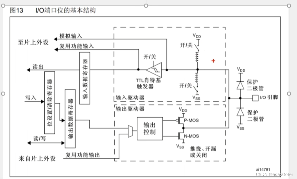
输入
上拉/下拉/浮空
为了给输入一个默认的输入电平
为了避免引脚悬空导致输入数据的不稳定,需要加上上拉电阻或下拉电阻
上拉电阻:浮空引脚,保证引脚的高电平
下拉电阻:浮空引脚,保证引脚的低电平
上拉输入:高电平输入
下拉输入:低电平输入
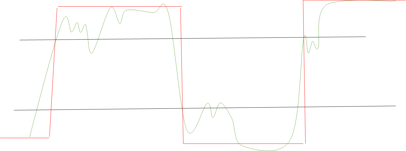
施密特触发器
对输入电压进行整形,防止干扰
如果输入电压大于某一阈值,输出就会瞬间升为高电平
如果输入电压小于某一阈值,输出就会瞬间降为低电平
片上外设
- 模拟输入 ADC等
- 复用输入 数字量
输出
- 输出寄存器:写某一位控制某一个引脚(用位设置和位清楚寄存器更好)
- 片上外设
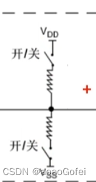
推挽/开漏/关闭输出方式
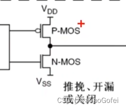
- 推挽输出
高低电平均有强驱动能力
P-MOS和N-MOS均有效
输出数据寄存器为1时,上管导通PMOS导通,下管NMOS断开,输出直接接到VDD,输出高电平
输出数据寄存器为0时,上管导通PMOS断开,下管NMOS导通,输出直接接到VSS,输出低电平
- 开漏输出
低电平有强驱动能力,高电平没有驱动能力
P-MOS无效,N-MOS有效
输出数据寄存器为1时,上管导通PMOS无效,下管NMOS断开,输出相当于断开,相当于高阻模式
输出数据寄存器为0时,上管导通PMOS无效,下管NMOS导通,输出直接接到VSS,输出低电平
开漏输出接外部的上拉5V电源
- 关闭输出
引脚配置为输入模式的时候
两个MOS管均无效
GPIO88种模式
复用输出
由片上外设进行输出
GPIO寄存器
端口配置寄存器_CRL
GPIOX_CRL
一共32位,每4位对应一个IO的配置,可配置8个引脚
端口输入数据寄存器_IDR
GPIOX_IDR
32位,低16位对应16个引脚
端口输出数据寄存器_ODR
GPIOX_ODR
32位,低16位对应16个引脚
端口位设置/清除寄存器_BSRR
GPIOX_BSRR
32位,高16位用于进行位清除,低16位用于进行位设置
端口位清除寄存器_BRR
32位,低16位用于进行位清除
端口配置锁定寄存器
端口锁定
例子
点灯
main.cpp
#include "stm32f10x.h"
#include "Delay.h"int main()
{// 初始化APB2外设时钟RCC_APB2PeriphClockCmd(RCC_APB2Periph_GPIOA,ENABLE); // 配置GPIO - ODR/CLRGPIO_InitTypeDef GPIO_InitStructure;			// 配置结构体GPIO_InitStructure.GPIO_Mode=GPIO_Mode_Out_PP; 	// GPIO_Mode_Out_PP 推挽输出
//	GPIO_InitStructure.GPIO_Mode=GPIO_Mode_Out_OD; 	// GPIO_Mode_Out_OD 开漏输出 	GPIO_InitStructure.GPIO_Pin=GPIO_Pin_0;			// GPIOA的0号引脚GPIO_InitStructure.GPIO_Speed=GPIO_Speed_50MHz; // 50MHZ GPIO_Init(GPIOA,&GPIO_InitStructure); // A0推挽输出//	GPIO_SetBits(GPIOA,GPIO_Pin_0); 	// 设置为高电平
//	GPIO_ResetBits(GPIOA,GPIO_Pin_0); 	// 设置为低电平
//	GPIO_Write();
//	GPIO_WriteBit(GPIOA,GPIO_Pin_0,Bit_RESET); // Bit_RESET 低电平
//	GPIO_WriteBit(GPIOA,GPIO_Pin_0,Bit_SET); // Bit_SET 高电平while (1){
//		GPIO_WriteBit(GPIOA,GPIO_Pin_0,Bit_RESET); 	// Bit_RESET 低电平GPIO_ResetBits(GPIOA,GPIO_Pin_0);			// version2Delay_ms(500);
//		GPIO_WriteBit(GPIOA,GPIO_Pin_0,Bit_SET); 	// Bit_SET 高电平GPIO_SetBits(GPIOA,GPIO_Pin_0);				// version2Delay_ms(500);}
}
delay.c
#include "stm32f10x.h"/*** @brief  微秒级延时* @param  xus 延时时长,范围:0~233015* @retval 无*/
void Delay_us(uint32_t xus)
{SysTick->LOAD = 72 * xus;				//设置定时器重装值SysTick->VAL = 0x00;					//清空当前计数值SysTick->CTRL = 0x00000005;				//设置时钟源为HCLK,启动定时器while(!(SysTick->CTRL & 0x00010000));	//等待计数到0SysTick->CTRL = 0x00000004;				//关闭定时器
}/*** @brief  毫秒级延时* @param  xms 延时时长,范围:0~4294967295* @retval 无*/
void Delay_ms(uint32_t xms)
{while(xms--){Delay_us(1000);}
}/*** @brief  秒级延时* @param  xs 延时时长,范围:0~4294967295* @retval 无*/
void Delay_s(uint32_t xs)
{while(xs--){Delay_ms(1000);}
}
流水灯
#include "stm32f10x.h"
#include "Delay.h"int main()
{// 初始化APB2外设时钟RCC_APB2PeriphClockCmd(RCC_APB2Periph_GPIOA,ENABLE); /* ====== 流水灯 ====== */// 配置GPIO - ODR/CLR registerGPIO_InitTypeDef GPIO_InitStructure;			// 配置结构体GPIO_InitStructure.GPIO_Mode=GPIO_Mode_Out_PP; 	// GPIO_Mode_Out_PP 推挽输出	/** #define GPIO_Pin_0                 ((uint16_t)0x0001)* #define GPIO_Pin_1                 ((uint16_t)0x0002)* #define GPIO_Pin_2                 ((uint16_t)0x0004)* #define GPIO_Pin_3                 ((uint16_t)0x0008)* #define GPIO_Pin_4                 ((uint16_t)0x0010)* #define GPIO_Pin_5                 ((uint16_t)0x0020)* #define GPIO_Pin_6                 ((uint16_t)0x0040)* #define GPIO_Pin_7                 ((uint16_t)0x0080)* GPIO_Pin_0 | GPIO_Pin_1 | GPIO_Pin_2 | GPIO_Pin_3 | GPIO_Pin_4 | GPIO_Pin_5 | GPIO_Pin_6 | GPIO_Pin_7* 等价于 0x0001 | 0x0002 ... 位之间并不冲突*/
//	GPIO_InitStructure.GPIO_Pin=GPIO_Pin_0 | GPIO_Pin_1 | GPIO_Pin_2 | GPIO_Pin_3 | GPIO_Pin_4 | GPIO_Pin_5 | GPIO_Pin_6 | GPIO_Pin_7;			// GPIOA的0号引脚GPIO_InitStructure.GPIO_Pin=GPIO_Pin_All;GPIO_InitStructure.GPIO_Speed=GPIO_Speed_50MHz; // 50MHZ GPIO_Init(GPIOA,&GPIO_InitStructure); // A0推挽输出while (1){for (int i=0;i<8;i++){GPIO_Write(GPIOA,~(0x0001<<i));
//			GPIO_WriteBit(GPIOA,GPIO_Pin_0,Bit_RESET);Delay_ms(100);}}
}
蜂鸣器
#include "stm32f10x.h"
#include "Delay.h"int main()
{// 初始化APB2外设时钟RCC_APB2PeriphClockCmd(RCC_APB2Periph_GPIOB,ENABLE); // 配置GPIO - ODR/CLRGPIO_InitTypeDef GPIO_InitStructure;			// 配置结构体GPIO_InitStructure.GPIO_Mode=GPIO_Mode_Out_PP; 	// GPIO_Mode_Out_PP 推挽输出
//	GPIO_InitStructure.GPIO_Mode=GPIO_Mode_Out_OD; 	// GPIO_Mode_Out_OD 开漏输出 	GPIO_InitStructure.GPIO_Pin= GPIO_Pin_12;			// GPIOA的0号引脚GPIO_InitStructure.GPIO_Speed=GPIO_Speed_50MHz; // 50MHZ GPIO_Init(GPIOB,&GPIO_InitStructure); // A0推挽输出//	GPIO_SetBits(GPIOB,GPIO_Pin_12); 	// 设置为高电平
//	GPIO_ResetBits(GPIOB,GPIO_Pin_12); 	// 设置为低电平
//	GPIO_WriteBit(GPIOB,GPIO_Pin_12,Bit_RESET); // Bit_RESET 低电平
//	GPIO_WriteBit(GPIOB,GPIO_Pin_12,Bit_SET); // Bit_SET 高电平while (1){
//		GPIO_WriteBit(GPIOB,GPIO_Pin_0,Bit_RESET); 	// Bit_RESET 低电平GPIO_ResetBits(GPIOB,GPIO_Pin_12);			// version2Delay_ms(500);
//		GPIO_WriteBit(GPIOB,GPIO_Pin_12,Bit_SET); 	// Bit_SET 高电平GPIO_SetBits(GPIOB,GPIO_Pin_12);				// version2Delay_ms(500);}}
按键和灯
main.c
#include "stm32f10x.h"
#include "Delay.h"
#include "LED.h"
#include "key.h"int main()
{uint8_t keyNum=0;LED_Init();Key_Init();while (1){keyNum=key_getNum();switch (keyNum){case 1: {LED_ON(1);LED_OFF(2);keyNum=0;break;}case 11: {LED_ON(2);LED_OFF(1);keyNum=0;break;}default: break;}/* turn 切换*/
//		if (keyNum==1)
//		{
//			LED_ON(1);
//		}
//		if (keyNum==11)
//		{
//			LED_OFF(1);
//		}
//		}
}
LED.h
#ifndef __LED_H__
#define __LED_H__void LED_Init();
void LED_ON(unsigned char pin_num);
void LED_OFF(unsigned char pin_num);
void LED_Turn(unsigned char pin_num);#endif
LED.c
#include "stm32f10x.h"
#include "LED.h"void LED_Init()
{// 初始化APB2外设时钟RCC_APB2PeriphClockCmd(RCC_APB2Periph_GPIOA,ENABLE); // 配置GPIO - ODR/CLRGPIO_InitTypeDef GPIO_InitStructure;			// 配置结构体GPIO_InitStructure.GPIO_Mode=GPIO_Mode_Out_PP; 	// GPIO_Mode_Out_PP 推挽输出
//	GPIO_InitStructure.GPIO_Mode=GPIO_Mode_Out_OD; 	// GPIO_Mode_Out_OD 开漏输出 	GPIO_InitStructure.GPIO_Pin= GPIO_Pin_1 | GPIO_Pin_2;			// GPIOA的0号引脚GPIO_InitStructure.GPIO_Speed=GPIO_Speed_50MHz; // 50MHZ GPIO_Init(GPIOA,&GPIO_InitStructure); // A0推挽输出// 默认输出高电平 不点灯GPIO_SetBits(GPIOA,GPIO_Pin_1 | GPIO_Pin_2);
}void LED_ON(unsigned char pin_num)
{switch (pin_num){case 0: {GPIO_ResetBits(GPIOA,GPIO_Pin_0);break;}case 1: {GPIO_ResetBits(GPIOA,GPIO_Pin_1);break;}case 2: {GPIO_ResetBits(GPIOA,GPIO_Pin_2);break;}case 3: {GPIO_ResetBits(GPIOA,GPIO_Pin_3);break;}case 4: {GPIO_ResetBits(GPIOA,GPIO_Pin_4);break;}case 5: {GPIO_ResetBits(GPIOA,GPIO_Pin_5);break;}case 6: {GPIO_ResetBits(GPIOA,GPIO_Pin_6);break;}case 7: {GPIO_ResetBits(GPIOA,GPIO_Pin_7);break;}		}
}void LED_OFF(unsigned char pin_num)
{switch (pin_num){case 0: {GPIO_SetBits(GPIOA,GPIO_Pin_0);break;}case 1: {GPIO_SetBits(GPIOA,GPIO_Pin_1);break;}case 2: {GPIO_SetBits(GPIOA,GPIO_Pin_2);break;}case 3: {GPIO_SetBits(GPIOA,GPIO_Pin_3);break;}case 4: {GPIO_SetBits(GPIOA,GPIO_Pin_4);break;}case 5: {GPIO_SetBits(GPIOA,GPIO_Pin_5);break;}case 6: {GPIO_SetBits(GPIOA,GPIO_Pin_6);break;}case 7: {GPIO_SetBits(GPIOA,GPIO_Pin_7);break;}		}
}void LED_Turn(unsigned char pin_num)
{switch (pin_num){case 0: {if (GPIO_ReadOutputDataBit(GPIOA,GPIO_Pin_0)==0){GPIO_SetBits(GPIOA,GPIO_Pin_0);}else if (GPIO_ReadOutputDataBit(GPIOA,GPIO_Pin_0)==1){GPIO_ResetBits(GPIOA,GPIO_Pin_0);}break;}case 1: {			if (GPIO_ReadOutputDataBit(GPIOA,GPIO_Pin_1)==0){GPIO_SetBits(GPIOA,GPIO_Pin_1);}else if (GPIO_ReadOutputDataBit(GPIOA,GPIO_Pin_1)==1){GPIO_ResetBits(GPIOA,GPIO_Pin_1);}break;}case 2: {			if (GPIO_ReadOutputDataBit(GPIOA,GPIO_Pin_2)==0){GPIO_SetBits(GPIOA,GPIO_Pin_2);}else if (GPIO_ReadOutputDataBit(GPIOA,GPIO_Pin_2)==1){GPIO_ResetBits(GPIOA,GPIO_Pin_2);}break;}case 3: {			if (GPIO_ReadOutputDataBit(GPIOA,GPIO_Pin_3)==0){GPIO_SetBits(GPIOA,GPIO_Pin_3);}else if (GPIO_ReadOutputDataBit(GPIOA,GPIO_Pin_3)==1){GPIO_ResetBits(GPIOA,GPIO_Pin_3);}break;}case 4: {			if (GPIO_ReadOutputDataBit(GPIOA,GPIO_Pin_4)==0){GPIO_SetBits(GPIOA,GPIO_Pin_4);}else if (GPIO_ReadOutputDataBit(GPIOA,GPIO_Pin_4)==1){GPIO_ResetBits(GPIOA,GPIO_Pin_4);}break;}case 5: {			if (GPIO_ReadOutputDataBit(GPIOA,GPIO_Pin_5)==0){GPIO_SetBits(GPIOA,GPIO_Pin_5);}else if (GPIO_ReadOutputDataBit(GPIOA,GPIO_Pin_5)==1){GPIO_ResetBits(GPIOA,GPIO_Pin_5);}break;}case 6: {			if (GPIO_ReadOutputDataBit(GPIOA,GPIO_Pin_6)==0){GPIO_SetBits(GPIOA,GPIO_Pin_6);}else if (GPIO_ReadOutputDataBit(GPIOA,GPIO_Pin_6)==1){GPIO_ResetBits(GPIOA,GPIO_Pin_6);}break;}case 7: {			if (GPIO_ReadOutputDataBit(GPIOA,GPIO_Pin_7)==0){GPIO_SetBits(GPIOA,GPIO_Pin_7);}else if (GPIO_ReadOutputDataBit(GPIOA,GPIO_Pin_7)==1){GPIO_ResetBits(GPIOA,GPIO_Pin_7);}break;}	}
}
key.h
#ifndef __KEY_H__
#define __KEY_H__void Key_Init();
uint8_t key_getNum();
#endif
key.c
#include "stm32f10x.h"
#include "key.h"
#include "Delay.h"void Key_Init()
{// 初始化APB2外设时钟RCC_APB2PeriphClockCmd(RCC_APB2Periph_GPIOB,ENABLE);// 配置GPIO - ODR/CLRGPIO_InitTypeDef GPIO_InitStructure;			// 配置结构体GPIO_InitStructure.GPIO_Mode=GPIO_Mode_IPU; 	// GPIO_Mode_IPU 上拉输入 - 根据原理图(内部 上拉输入配置)GPIO_InitStructure.GPIO_Pin= GPIO_Pin_1 | GPIO_Pin_11;			// GPIOB的1,11号引脚GPIO_InitStructure.GPIO_Speed=GPIO_Speed_50MHz; // 50MHZ 仅与输入有关GPIO_Init(GPIOB,&GPIO_InitStructure); 			// B0推挽输出
}uint8_t key_getNum()
{uint8_t keyNum=0;/** GPIO_ReadInputDataBit 读取输入数据寄存器某一端口(引脚)的输入值,高低电平* GPIO_ReadInputData   读取整个输入数据寄存器* GPIO_ReadOutputDataBit 读取输出数据寄存器某一个位,输出模式下,用来看一下自己输出的是什么* GPIO_ReadOutputData 读取整个输出数据寄存器*/ // 输入数据if (GPIO_ReadInputDataBit(GPIOB,GPIO_Pin_1)==0){Delay_ms(20);while (GPIO_ReadInputDataBit(GPIOB,GPIO_Pin_1)==0);Delay_ms(20);keyNum=1;}if (GPIO_ReadInputDataBit(GPIOB,GPIO_Pin_11)==0){Delay_ms(20);while (GPIO_ReadInputDataBit(GPIOB,GPIO_Pin_11)==0);Delay_ms(20);keyNum=11;}return keyNum;
}
蜂鸣器和光敏电阻
main.c
#include "stm32f10x.h"
#include "Delay.h"
#include "LED.h"
#include "key.h"
#include "Buzzer.h"
#include "PhotoSensor.h"int main()
{uint8_t keyNum=0;Buzzer_Init(12);PhotoSensor_Init(13);while (1){/* === 蜂鸣器 ===*/
//		Buzzer_Turn(12);
//		Delay_ms(500);
//		Buzzer_Turn(12);
//		Delay_ms(500);/* === 光敏传感器 ===*/
//		PhotoSensor_Turn(13);
//		Delay_ms(500);
//		PhotoSensor_Turn(13);
//		Delay_ms(500);/* === 光敏传感器2 ,光敏传感器控制蜂鸣器 ===*/if (PhotoSensor_Get(13)==1){Buzzer_ON(12);}else{Buzzer_OFF(12);}}
}
Buzzer.h
#ifndef __BUZZER_H__
#define __BUZZER_H__void Buzzer_Init(unsigned char pin_num);
void Buzzer_ON(unsigned char pin_num);
void Buzzer_OFF(unsigned char pin_num);
void Buzzer_Turn(unsigned char pin_num);#endif
Buzzer.c
#include "stm32f10x.h"
#include "Buzzer.h"void Buzzer_Init(unsigned char pin_num)
{uint16_t GPIO_Pin_num=0;switch (pin_num){case 0: {GPIO_Pin_num=GPIO_Pin_0;break;}case 1: {GPIO_Pin_num=GPIO_Pin_1;break;}case 2: {GPIO_Pin_num=GPIO_Pin_2;break;}case 3: {GPIO_Pin_num=GPIO_Pin_3;break;}case 4: {GPIO_Pin_num=GPIO_Pin_4;break;}case 5: {GPIO_Pin_num=GPIO_Pin_5;break;}case 6: {GPIO_Pin_num=GPIO_Pin_6;break;}case 7: {GPIO_Pin_num=GPIO_Pin_7;break;}case 8: {GPIO_Pin_num=GPIO_Pin_8;break;}case 9: {GPIO_Pin_num=GPIO_Pin_9;break;}case 10: {GPIO_Pin_num=GPIO_Pin_10;break;}case 11: {GPIO_Pin_num=GPIO_Pin_11;break;}case 12: {GPIO_Pin_num=GPIO_Pin_12;break;}case 13: {GPIO_Pin_num=GPIO_Pin_13;break;}case 14: {GPIO_Pin_num=GPIO_Pin_14;break;}}// 初始化APB2外设时钟RCC_APB2PeriphClockCmd(RCC_APB2Periph_GPIOB,ENABLE); // 配置GPIO - ODR/CLRGPIO_InitTypeDef GPIO_InitStructure;			// 配置结构体GPIO_InitStructure.GPIO_Mode=GPIO_Mode_Out_PP; 	// GPIO_Mode_Out_PP 推挽输出
//	GPIO_InitStructure.GPIO_Mode=GPIO_Mode_Out_OD; 	// GPIO_Mode_Out_OD 开漏输出 	GPIO_InitStructure.GPIO_Pin= GPIO_Pin_num;			// GPIOB的0号引脚GPIO_InitStructure.GPIO_Speed=GPIO_Speed_50MHz; // 50MHZ GPIO_Init(GPIOB,&GPIO_InitStructure); // A0推挽输出// 默认输出高电平 不点灯GPIO_SetBits(GPIOB,GPIO_Pin_num);
}void Buzzer_ON(unsigned char pin_num)
{switch (pin_num){case 0: {GPIO_ResetBits(GPIOB,GPIO_Pin_0);break;}case 1: {GPIO_ResetBits(GPIOB,GPIO_Pin_1);break;}case 2: {GPIO_ResetBits(GPIOB,GPIO_Pin_2);break;}case 3: {GPIO_ResetBits(GPIOB,GPIO_Pin_3);break;}case 4: {GPIO_ResetBits(GPIOB,GPIO_Pin_4);break;}case 5: {GPIO_ResetBits(GPIOB,GPIO_Pin_5);break;}case 6: {GPIO_ResetBits(GPIOB,GPIO_Pin_6);break;}case 7: {GPIO_ResetBits(GPIOB,GPIO_Pin_7);break;}case 8: {GPIO_ResetBits(GPIOB,GPIO_Pin_8);break;}case 9: {GPIO_ResetBits(GPIOB,GPIO_Pin_9);break;}case 10: {GPIO_ResetBits(GPIOB,GPIO_Pin_10);break;}case 11: {GPIO_ResetBits(GPIOB,GPIO_Pin_11);break;}case 12: {GPIO_ResetBits(GPIOB,GPIO_Pin_12);break;}case 13: {GPIO_ResetBits(GPIOB,GPIO_Pin_13);break;}case 14: {GPIO_ResetBits(GPIOB,GPIO_Pin_14);break;}case 15: {GPIO_ResetBits(GPIOB,GPIO_Pin_15);break;}		}
}void Buzzer_OFF(unsigned char pin_num)
{switch (pin_num){case 0: {GPIO_SetBits(GPIOB,GPIO_Pin_0);break;}case 1: {GPIO_SetBits(GPIOB,GPIO_Pin_1);break;}case 2: {GPIO_SetBits(GPIOB,GPIO_Pin_2);break;}case 3: {GPIO_SetBits(GPIOB,GPIO_Pin_3);break;}case 4: {GPIO_SetBits(GPIOB,GPIO_Pin_4);break;}case 5: {GPIO_SetBits(GPIOB,GPIO_Pin_5);break;}case 6: {GPIO_SetBits(GPIOB,GPIO_Pin_6);break;}case 7: {GPIO_SetBits(GPIOB,GPIO_Pin_7);break;}case 8: {GPIO_SetBits(GPIOB,GPIO_Pin_8);break;}case 9: {GPIO_SetBits(GPIOB,GPIO_Pin_9);break;}case 10: {GPIO_SetBits(GPIOB,GPIO_Pin_10);break;}case 11: {GPIO_SetBits(GPIOB,GPIO_Pin_11);break;}case 12: {GPIO_SetBits(GPIOB,GPIO_Pin_12);break;}case 13: {GPIO_SetBits(GPIOB,GPIO_Pin_13);break;}case 14: {GPIO_SetBits(GPIOB,GPIO_Pin_14);break;}case 15: {GPIO_SetBits(GPIOB,GPIO_Pin_15);break;}			}
}void Buzzer_Turn(unsigned char pin_num)
{// version 2uint16_t GPIO_Pin_num=0;switch (pin_num){case 0: {GPIO_Pin_num=GPIO_Pin_0;break;}case 1: {GPIO_Pin_num=GPIO_Pin_1;break;}case 2: {GPIO_Pin_num=GPIO_Pin_2;break;}case 3: {GPIO_Pin_num=GPIO_Pin_3;break;}case 4: {GPIO_Pin_num=GPIO_Pin_4;break;}case 5: {GPIO_Pin_num=GPIO_Pin_5;break;}case 6: {GPIO_Pin_num=GPIO_Pin_6;break;}case 7: {GPIO_Pin_num=GPIO_Pin_7;break;}case 8: {GPIO_Pin_num=GPIO_Pin_8;break;}case 9: {GPIO_Pin_num=GPIO_Pin_9;break;}case 10: {GPIO_Pin_num=GPIO_Pin_10;break;}case 11: {GPIO_Pin_num=GPIO_Pin_11;break;}case 12: {GPIO_Pin_num=GPIO_Pin_12;break;}case 13: {GPIO_Pin_num=GPIO_Pin_13;break;}case 14: {GPIO_Pin_num=GPIO_Pin_14;break;}}if (GPIO_ReadOutputDataBit(GPIOB,GPIO_Pin_num)==0){GPIO_SetBits(GPIOB,GPIO_Pin_num);}else if (GPIO_ReadOutputDataBit(GPIOB,GPIO_Pin_num)==1){GPIO_ResetBits(GPIOB,GPIO_Pin_num);}// version 1
//	switch (pin_num)
//	{
//		case 0: {
//			if (GPIO_ReadOutputDataBit(GPIOB,GPIO_Pin_0)==0)
//			{
//				GPIO_SetBits(GPIOB,GPIO_Pin_0);
//			}
//			else if (GPIO_ReadOutputDataBit(GPIOB,GPIO_Pin_0)==1)
//			{
//				GPIO_ResetBits(GPIOB,GPIO_Pin_0);
//			}
//			break;
//		}
//		case 1: {
//			if (GPIO_ReadOutputDataBit(GPIOB,GPIO_Pin_1)==0)
//			{
//				GPIO_SetBits(GPIOB,GPIO_Pin_1);
//			}
//			else if (GPIO_ReadOutputDataBit(GPIOB,GPIO_Pin_1)==1)
//			{
//				GPIO_ResetBits(GPIOB,GPIO_Pin_1);
//			}
//			break;
//		}
//		case 2: {
//			if (GPIO_ReadOutputDataBit(GPIOB,GPIO_Pin_2)==0)
//			{
//				GPIO_SetBits(GPIOB,GPIO_Pin_2);
//			}
//			else if (GPIO_ReadOutputDataBit(GPIOB,GPIO_Pin_2)==1)
//			{
//				GPIO_ResetBits(GPIOB,GPIO_Pin_2);
//			}
//			break;
//		}
//		case 3: {
//			if (GPIO_ReadOutputDataBit(GPIOB,GPIO_Pin_3)==0)
//			{
//				GPIO_SetBits(GPIOB,GPIO_Pin_3);
//			}
//			else if (GPIO_ReadOutputDataBit(GPIOB,GPIO_Pin_3)==1)
//			{
//				GPIO_ResetBits(GPIOB,GPIO_Pin_3);
//			}
//			break;
//		}
//		case 4: {
//			if (GPIO_ReadOutputDataBit(GPIOB,GPIO_Pin_4)==0)
//			{
//				GPIO_SetBits(GPIOB,GPIO_Pin_4);
//			}
//			else if (GPIO_ReadOutputDataBit(GPIOB,GPIO_Pin_4)==1)
//			{
//				GPIO_ResetBits(GPIOB,GPIO_Pin_4);
//			}
//			break;
//		}
//		case 5: {
//			if (GPIO_ReadOutputDataBit(GPIOB,GPIO_Pin_5)==0)
//			{
//				GPIO_SetBits(GPIOB,GPIO_Pin_5);
//			}
//			else if (GPIO_ReadOutputDataBit(GPIOB,GPIO_Pin_5)==1)
//			{
//				GPIO_ResetBits(GPIOB,GPIO_Pin_5);
//			}
//			break;
//		}
//		case 6: {
//			if (GPIO_ReadOutputDataBit(GPIOB,GPIO_Pin_6)==0)
//			{
//				GPIO_SetBits(GPIOB,GPIO_Pin_6);
//			}
//			else if (GPIO_ReadOutputDataBit(GPIOB,GPIO_Pin_6)==1)
//			{
//				GPIO_ResetBits(GPIOB,GPIO_Pin_6);
//			}
//			break;
//		}
//		case 7: {
//			if (GPIO_ReadOutputDataBit(GPIOB,GPIO_Pin_7)==0)
//			{
//				GPIO_SetBits(GPIOB,GPIO_Pin_7);
//			}
//			else if (GPIO_ReadOutputDataBit(GPIOB,GPIO_Pin_7)==1)
//			{
//				GPIO_ResetBits(GPIOB,GPIO_Pin_7);
//			}
//			break;
//		}
//	}
}
photosensor.h
#ifndef __PHOTOSENSOR_H__
#define __PHOTOSENSOR_H__void PhotoSensor_Init(unsigned char pin_num);
void PhotoSensor_ON(unsigned char pin_num);
void PhotoSensor_OFF(unsigned char pin_num);
void PhotoSensor_Turn(unsigned char pin_num);
uint8_t PhotoSensor_Get(unsigned char pin_num);#endif
photosensor.c
#include "stm32f10x.h"
#include "PhotoSensor.h"void PhotoSensor_Init(unsigned char pin_num)
{uint16_t GPIO_Pin_num=0;switch (pin_num){case 0: {GPIO_Pin_num=GPIO_Pin_0;break;}case 1: {GPIO_Pin_num=GPIO_Pin_1;break;}case 2: {GPIO_Pin_num=GPIO_Pin_2;break;}case 3: {GPIO_Pin_num=GPIO_Pin_3;break;}case 4: {GPIO_Pin_num=GPIO_Pin_4;break;}case 5: {GPIO_Pin_num=GPIO_Pin_5;break;}case 6: {GPIO_Pin_num=GPIO_Pin_6;break;}case 7: {GPIO_Pin_num=GPIO_Pin_7;break;}case 8: {GPIO_Pin_num=GPIO_Pin_8;break;}case 9: {GPIO_Pin_num=GPIO_Pin_9;break;}case 10: {GPIO_Pin_num=GPIO_Pin_10;break;}case 11: {GPIO_Pin_num=GPIO_Pin_11;break;}case 12: {GPIO_Pin_num=GPIO_Pin_12;break;}case 13: {GPIO_Pin_num=GPIO_Pin_13;break;}case 14: {GPIO_Pin_num=GPIO_Pin_14;break;}}// 初始化APB2外设时钟RCC_APB2PeriphClockCmd(RCC_APB2Periph_GPIOB,ENABLE); // 配置GPIO - ODR/CLRGPIO_InitTypeDef GPIO_InitStructure;			// 配置结构体GPIO_InitStructure.GPIO_Mode=GPIO_Mode_IPU; 	// 上拉输入	GPIO_InitStructure.GPIO_Pin= GPIO_Pin_num;			// GPIOB的0号引脚GPIO_InitStructure.GPIO_Speed=GPIO_Speed_50MHz; // 50MHZ GPIO_Init(GPIOB,&GPIO_InitStructure);}void PhotoSensor_ON(unsigned char pin_num)
{switch (pin_num){case 0: {GPIO_ResetBits(GPIOB,GPIO_Pin_0);break;}case 1: {GPIO_ResetBits(GPIOB,GPIO_Pin_1);break;}case 2: {GPIO_ResetBits(GPIOB,GPIO_Pin_2);break;}case 3: {GPIO_ResetBits(GPIOB,GPIO_Pin_3);break;}case 4: {GPIO_ResetBits(GPIOB,GPIO_Pin_4);break;}case 5: {GPIO_ResetBits(GPIOB,GPIO_Pin_5);break;}case 6: {GPIO_ResetBits(GPIOB,GPIO_Pin_6);break;}case 7: {GPIO_ResetBits(GPIOB,GPIO_Pin_7);break;}case 8: {GPIO_ResetBits(GPIOB,GPIO_Pin_8);break;}case 9: {GPIO_ResetBits(GPIOB,GPIO_Pin_9);break;}case 10: {GPIO_ResetBits(GPIOB,GPIO_Pin_10);break;}case 11: {GPIO_ResetBits(GPIOB,GPIO_Pin_11);break;}case 12: {GPIO_ResetBits(GPIOB,GPIO_Pin_12);break;}case 13: {GPIO_ResetBits(GPIOB,GPIO_Pin_13);break;}case 14: {GPIO_ResetBits(GPIOB,GPIO_Pin_14);break;}case 15: {GPIO_ResetBits(GPIOB,GPIO_Pin_15);break;}		}
}void PhotoSensor_OFF(unsigned char pin_num)
{switch (pin_num){case 0: {GPIO_SetBits(GPIOB,GPIO_Pin_0);break;}case 1: {GPIO_SetBits(GPIOB,GPIO_Pin_1);break;}case 2: {GPIO_SetBits(GPIOB,GPIO_Pin_2);break;}case 3: {GPIO_SetBits(GPIOB,GPIO_Pin_3);break;}case 4: {GPIO_SetBits(GPIOB,GPIO_Pin_4);break;}case 5: {GPIO_SetBits(GPIOB,GPIO_Pin_5);break;}case 6: {GPIO_SetBits(GPIOB,GPIO_Pin_6);break;}case 7: {GPIO_SetBits(GPIOB,GPIO_Pin_7);break;}case 8: {GPIO_SetBits(GPIOB,GPIO_Pin_8);break;}case 9: {GPIO_SetBits(GPIOB,GPIO_Pin_9);break;}case 10: {GPIO_SetBits(GPIOB,GPIO_Pin_10);break;}case 11: {GPIO_SetBits(GPIOB,GPIO_Pin_11);break;}case 12: {GPIO_SetBits(GPIOB,GPIO_Pin_12);break;}case 13: {GPIO_SetBits(GPIOB,GPIO_Pin_13);break;}case 14: {GPIO_SetBits(GPIOB,GPIO_Pin_14);break;}case 15: {GPIO_SetBits(GPIOB,GPIO_Pin_15);break;}			}
}void PhotoSensor_Turn(unsigned char pin_num)
{// version 2uint16_t GPIO_Pin_num=0;switch (pin_num){case 0: {GPIO_Pin_num=GPIO_Pin_0;break;}case 1: {GPIO_Pin_num=GPIO_Pin_1;break;}case 2: {GPIO_Pin_num=GPIO_Pin_2;break;}case 3: {GPIO_Pin_num=GPIO_Pin_3;break;}case 4: {GPIO_Pin_num=GPIO_Pin_4;break;}case 5: {GPIO_Pin_num=GPIO_Pin_5;break;}case 6: {GPIO_Pin_num=GPIO_Pin_6;break;}case 7: {GPIO_Pin_num=GPIO_Pin_7;break;}case 8: {GPIO_Pin_num=GPIO_Pin_8;break;}case 9: {GPIO_Pin_num=GPIO_Pin_9;break;}case 10: {GPIO_Pin_num=GPIO_Pin_10;break;}case 11: {GPIO_Pin_num=GPIO_Pin_11;break;}case 12: {GPIO_Pin_num=GPIO_Pin_12;break;}case 13: {GPIO_Pin_num=GPIO_Pin_13;break;}case 14: {GPIO_Pin_num=GPIO_Pin_14;break;}}if (GPIO_ReadOutputDataBit(GPIOB,GPIO_Pin_num)==0){GPIO_SetBits(GPIOB,GPIO_Pin_num);}else if (GPIO_ReadOutputDataBit(GPIOB,GPIO_Pin_num)==1){GPIO_ResetBits(GPIOB,GPIO_Pin_num);}// version 1
//	switch (pin_num)
//	{
//		case 0: {
//			if (GPIO_ReadOutputDataBit(GPIOB,GPIO_Pin_0)==0)
//			{
//				GPIO_SetBits(GPIOB,GPIO_Pin_0);
//			}
//			else if (GPIO_ReadOutputDataBit(GPIOB,GPIO_Pin_0)==1)
//			{
//				GPIO_ResetBits(GPIOB,GPIO_Pin_0);
//			}
//			break;
//		}
//		case 1: {
//			if (GPIO_ReadOutputDataBit(GPIOB,GPIO_Pin_1)==0)
//			{
//				GPIO_SetBits(GPIOB,GPIO_Pin_1);
//			}
//			else if (GPIO_ReadOutputDataBit(GPIOB,GPIO_Pin_1)==1)
//			{
//				GPIO_ResetBits(GPIOB,GPIO_Pin_1);
//			}
//			break;
//		}
//		case 2: {
//			if (GPIO_ReadOutputDataBit(GPIOB,GPIO_Pin_2)==0)
//			{
//				GPIO_SetBits(GPIOB,GPIO_Pin_2);
//			}
//			else if (GPIO_ReadOutputDataBit(GPIOB,GPIO_Pin_2)==1)
//			{
//				GPIO_ResetBits(GPIOB,GPIO_Pin_2);
//			}
//			break;
//		}
//		case 3: {
//			if (GPIO_ReadOutputDataBit(GPIOB,GPIO_Pin_3)==0)
//			{
//				GPIO_SetBits(GPIOB,GPIO_Pin_3);
//			}
//			else if (GPIO_ReadOutputDataBit(GPIOB,GPIO_Pin_3)==1)
//			{
//				GPIO_ResetBits(GPIOB,GPIO_Pin_3);
//			}
//			break;
//		}
//		case 4: {
//			if (GPIO_ReadOutputDataBit(GPIOB,GPIO_Pin_4)==0)
//			{
//				GPIO_SetBits(GPIOB,GPIO_Pin_4);
//			}
//			else if (GPIO_ReadOutputDataBit(GPIOB,GPIO_Pin_4)==1)
//			{
//				GPIO_ResetBits(GPIOB,GPIO_Pin_4);
//			}
//			break;
//		}
//		case 5: {
//			if (GPIO_ReadOutputDataBit(GPIOB,GPIO_Pin_5)==0)
//			{
//				GPIO_SetBits(GPIOB,GPIO_Pin_5);
//			}
//			else if (GPIO_ReadOutputDataBit(GPIOB,GPIO_Pin_5)==1)
//			{
//				GPIO_ResetBits(GPIOB,GPIO_Pin_5);
//			}
//			break;
//		}
//		case 6: {
//			if (GPIO_ReadOutputDataBit(GPIOB,GPIO_Pin_6)==0)
//			{
//				GPIO_SetBits(GPIOB,GPIO_Pin_6);
//			}
//			else if (GPIO_ReadOutputDataBit(GPIOB,GPIO_Pin_6)==1)
//			{
//				GPIO_ResetBits(GPIOB,GPIO_Pin_6);
//			}
//			break;
//		}
//		case 7: {
//			if (GPIO_ReadOutputDataBit(GPIOB,GPIO_Pin_7)==0)
//			{
//				GPIO_SetBits(GPIOB,GPIO_Pin_7);
//			}
//			else if (GPIO_ReadOutputDataBit(GPIOB,GPIO_Pin_7)==1)
//			{
//				GPIO_ResetBits(GPIOB,GPIO_Pin_7);
//			}
//			break;
//		}
//	}
}uint8_t PhotoSensor_Get(unsigned char pin_num)
{uint16_t GPIO_Pin_num=0;switch (pin_num){case 0: {GPIO_Pin_num=GPIO_Pin_0;break;}case 1: {GPIO_Pin_num=GPIO_Pin_1;break;}case 2: {GPIO_Pin_num=GPIO_Pin_2;break;}case 3: {GPIO_Pin_num=GPIO_Pin_3;break;}case 4: {GPIO_Pin_num=GPIO_Pin_4;break;}case 5: {GPIO_Pin_num=GPIO_Pin_5;break;}case 6: {GPIO_Pin_num=GPIO_Pin_6;break;}case 7: {GPIO_Pin_num=GPIO_Pin_7;break;}case 8: {GPIO_Pin_num=GPIO_Pin_8;break;}case 9: {GPIO_Pin_num=GPIO_Pin_9;break;}case 10: {GPIO_Pin_num=GPIO_Pin_10;break;}case 11: {GPIO_Pin_num=GPIO_Pin_11;break;}case 12: {GPIO_Pin_num=GPIO_Pin_12;break;}case 13: {GPIO_Pin_num=GPIO_Pin_13;break;}case 14: {GPIO_Pin_num=GPIO_Pin_14;break;}}return GPIO_ReadInputDataBit(GPIOB,GPIO_Pin_num);
}